DIY CHAIN DRIVEN ELECTRIC LONGBOARD
I decided I wanted some kind of mode of transport for mostly short journeys, like from the house to the train station, from home to school and back for the school pick-up. Yeah lazy I know but I want it to be fun too!
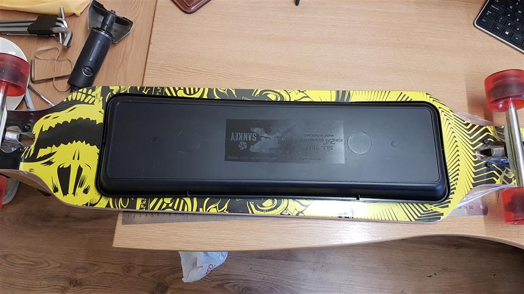
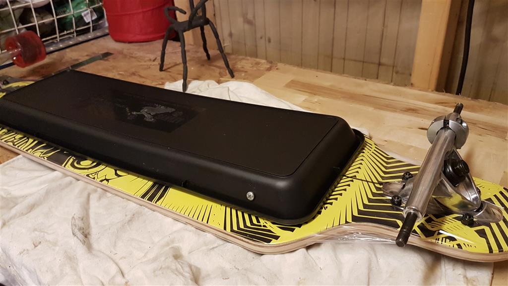
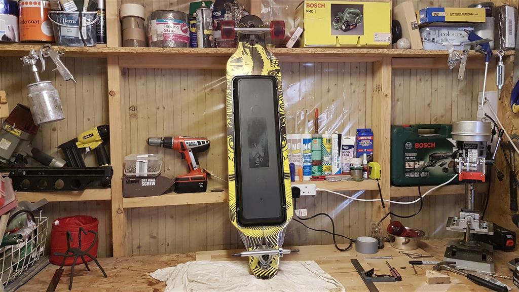
The board above is the one that I ordered online (eBay) for a steal! and is the one that's going to become a power board...
FYI, I was amazed at the quality of this board for the price! Most longboards start at around £100 for a decent board, but this one was just £35!! and glides along as smooth as a Gillette Mac 5! (or whatever they're up to nowadays, I don't know 'cause I don't shave any more!) soaking up all the bumps the extremely bumpy pavement down my road could throw at me.
FYI, I was amazed at the quality of this board for the price! Most longboards start at around £100 for a decent board, but this one was just £35!! and glides along as smooth as a Gillette Mac 5! (or whatever they're up to nowadays, I don't know 'cause I don't shave any more!) soaking up all the bumps the extremely bumpy pavement down my road could throw at me.
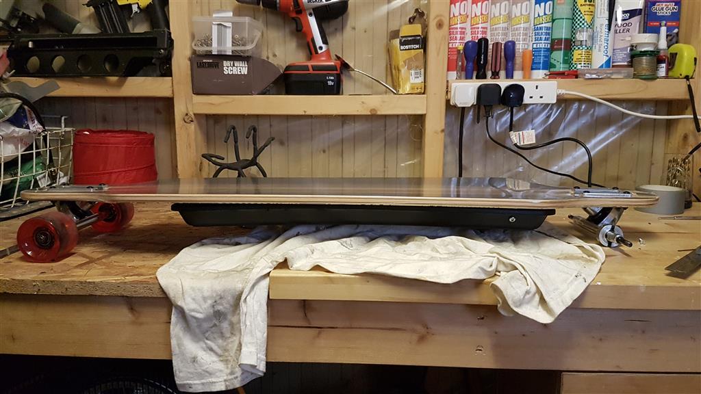
Below are some specs of the board:
- Deck length: approx 104 cm (41")
- Deck width: about 25 cm
- Deck: 9 ply maple wood (9 ply maple)
- Deck-top: black grip tape
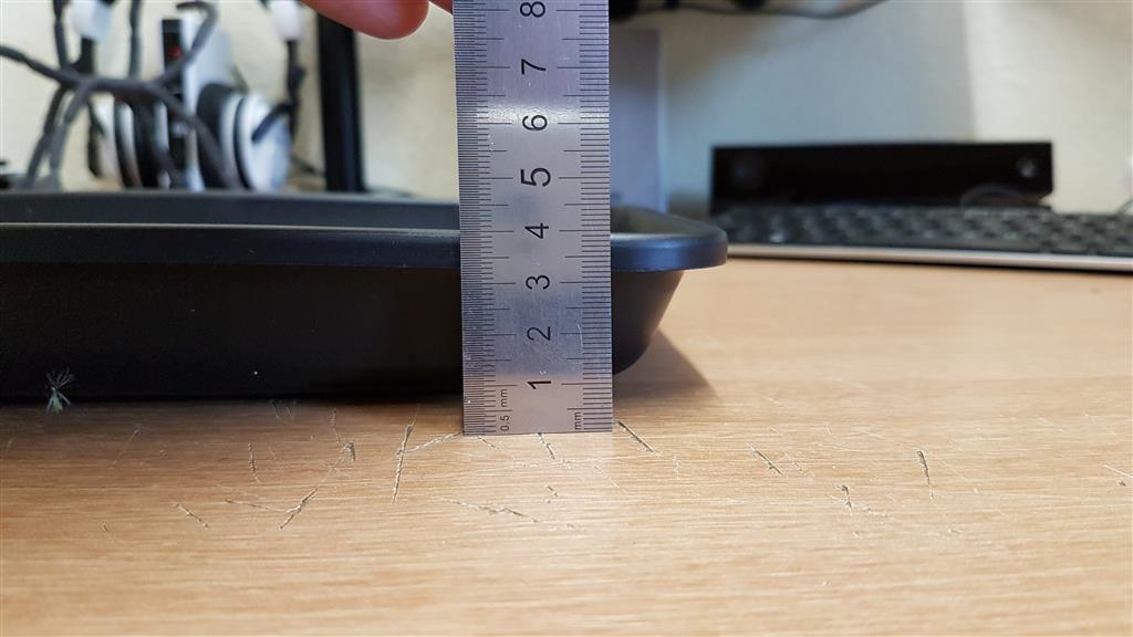
- Total height: about 12 cm
- Castors material: PU (Polyurethane)
- Castors Ø / Width: about 7 / 5 cm
- Hardness 85A
- Bearings: ABEC 9
- Axles material: Aluminum
- Axis mounting: Drop through
- User weight: recommended rider weight up to 85 kg
- Max. load: up to 100 kg
- The wheels need to be a minimum of 70mm diameter, preferably 80mm
- The wheels are made from PU (polyurethane) and are no harder than 85A
- Your motor has a low enough KV rating to haul your fat ass
- Your ESC (Speed Controller) has a high enough AMP rating for your batteries
The Build
I started by doing a whole load of research... Some long nights! If you search for 'electric longboard' on YouTube, you'll find a myriad of vlogs from people who've powered their own boards either from kits or a custom bespoke hand-made system.
Thanks to those videos I've been able to use the best features from all the different electric longboards and am now aware of all the pitfalls I may have encountered should I not have done my research first.
I'm not trying to take anything away from those guys powering their own boards, but almost every one was very poorly finished with perhaps some poorly made wooden boxes to house radio & electric gear, or Tupperware boxes screwed to the underside of the board, or even just strapped down with some aluminium, and motor mounts that are extremely rough and look unfinished, and that's just too ugly for me. So I'm setting out to make my powered board as 'pretty' as possible and as close to a shop bought electric longboard as possible. I'm basically testing out my engineering skills.
Thanks largely to an accumulation of tools over the years and more recently my awesome Dad for lending me some of his, I'm able to stretch myself technically in an attempt to produce something hopefully exquisite!
Power Train
I decided to go with a chain driven power train, rather than the more common method of a toothed belt and two pulleys. The reason for this was strength and durability. Lots of people who'd built their boards already complained that sometimes the belt slipped, or snapped or that it ran off the pulley, and I didn't want that so a chain and sprocket was the only way for me.
I found a great company on the web (after an exhaustive search), who supply all sorts of different steel sprockets and chains, there's a link to their website at the bottom of this paragraph.
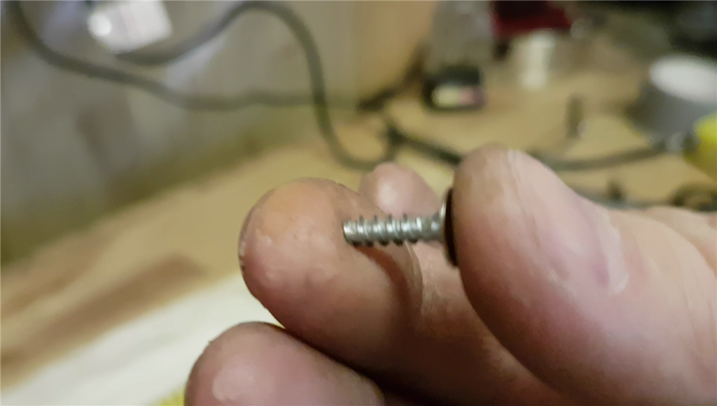
I chose a 6mm pitch steel chain sprocket for the motor and the hub, (no need for any bigger), and a tiny little 6mm pitch chain to connect it all up with. You literally only need a few inches of chain but they only sell it by the metre, but they're really inexpensive, so you can't complain.
I found a great company on the web (after an exhaustive search), who supply all sorts of different steel sprockets and chains, there's a link to their website at the bottom of this paragraph.
I chose a 6mm pitch steel chain sprocket for the motor and the hub, (no need for any bigger), and a tiny little 6mm pitch chain to connect it all up with. You literally only need a few inches of chain but they only sell it by the metre, but they're really inexpensive, so you can't complain.
The size of chain and sprocket you'd need is 04B and the pitch is 6mm, oh and simplex (single) not duplex.
Source: http://www.technobotsonline.com/
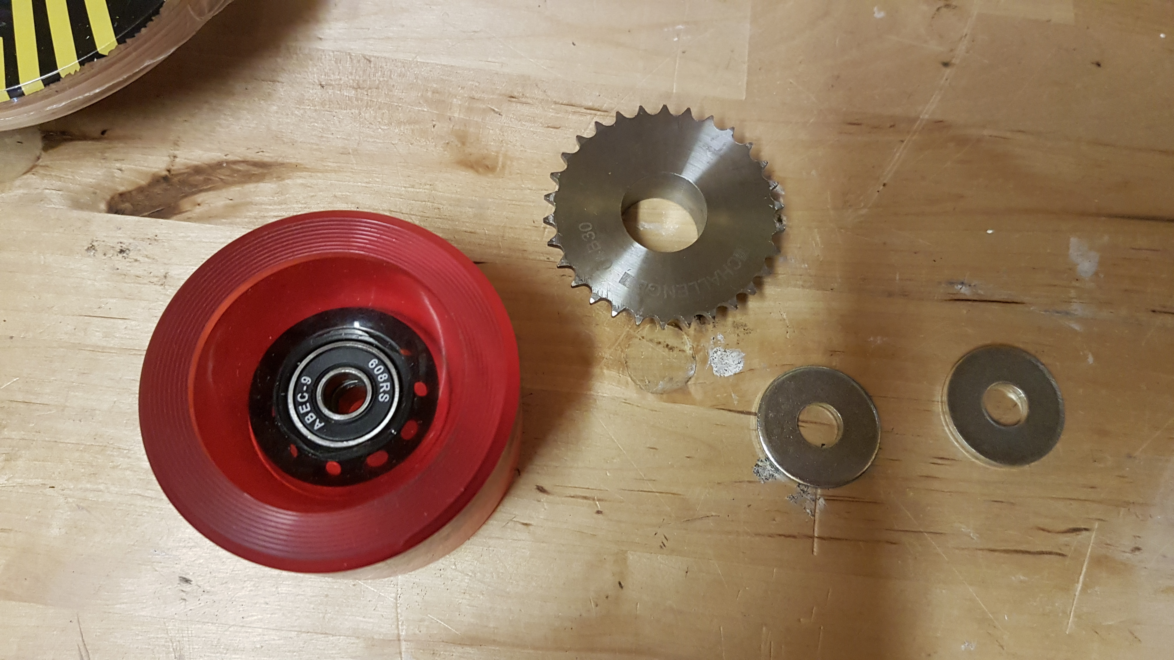
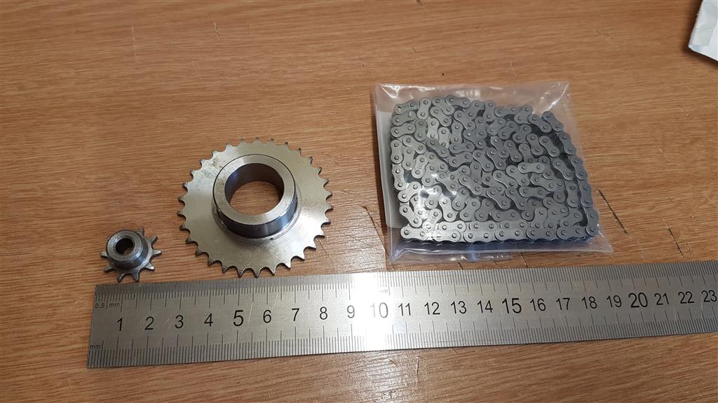
Here are the (from left to right); pinion (goes on the motor), main drive sprocket (on the wheel) and chain.
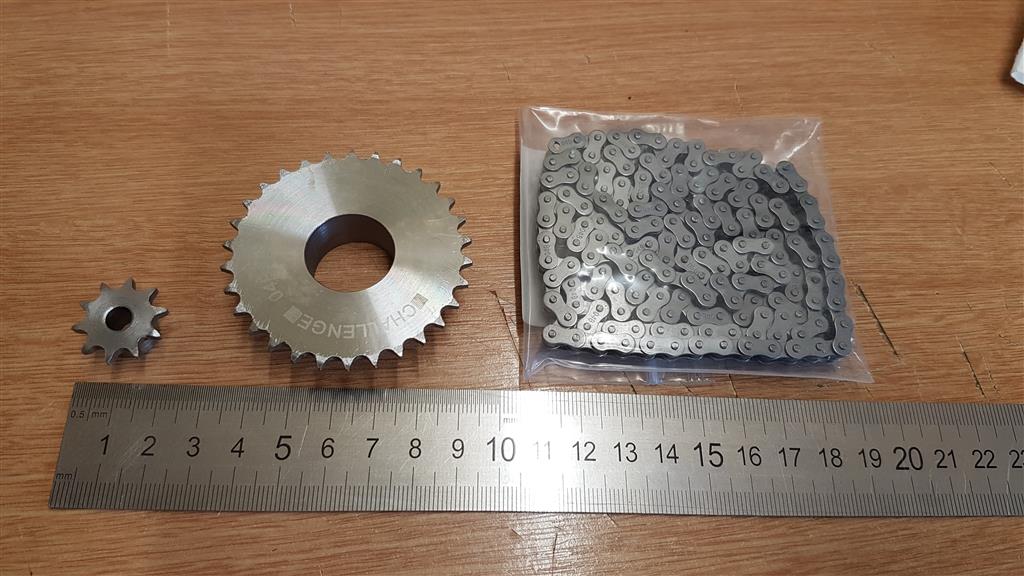
These are the sprockets I ordered:
| 04B Steel Chain Sprocket 6mm - 10T | £3.80 |
| 04B Steel Chain Sprocket 6mm - 30T Custom Bore Size: 21mm | £3.50 |
As you can see from what I ordered (above), I paid to have the pinion tapped with an M4 grub screw, but they didn't do it.
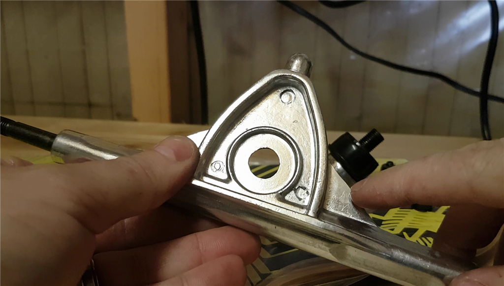
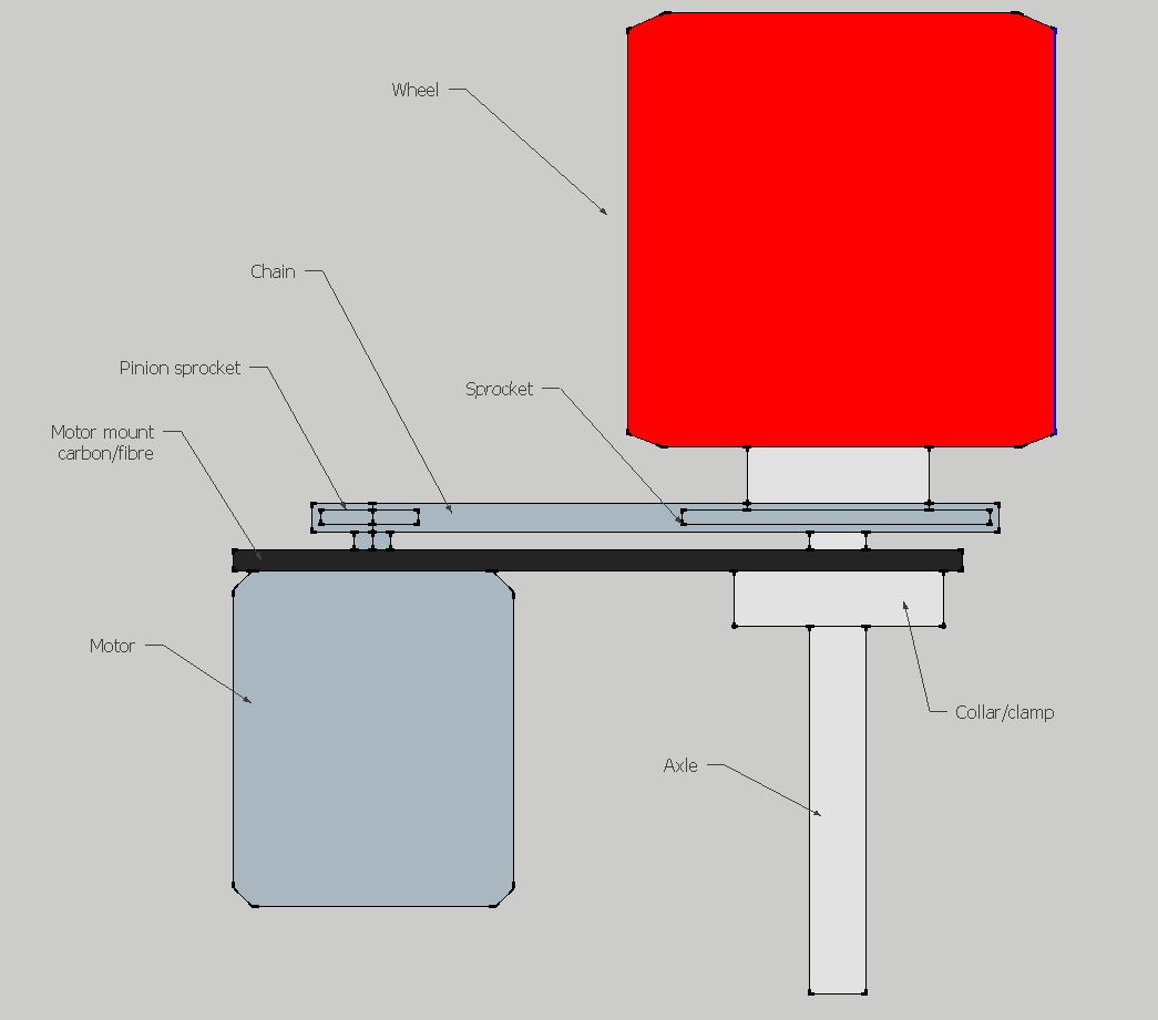
Below is a diagram of how the electric motor will be connected to one of the wheels via a small chain.
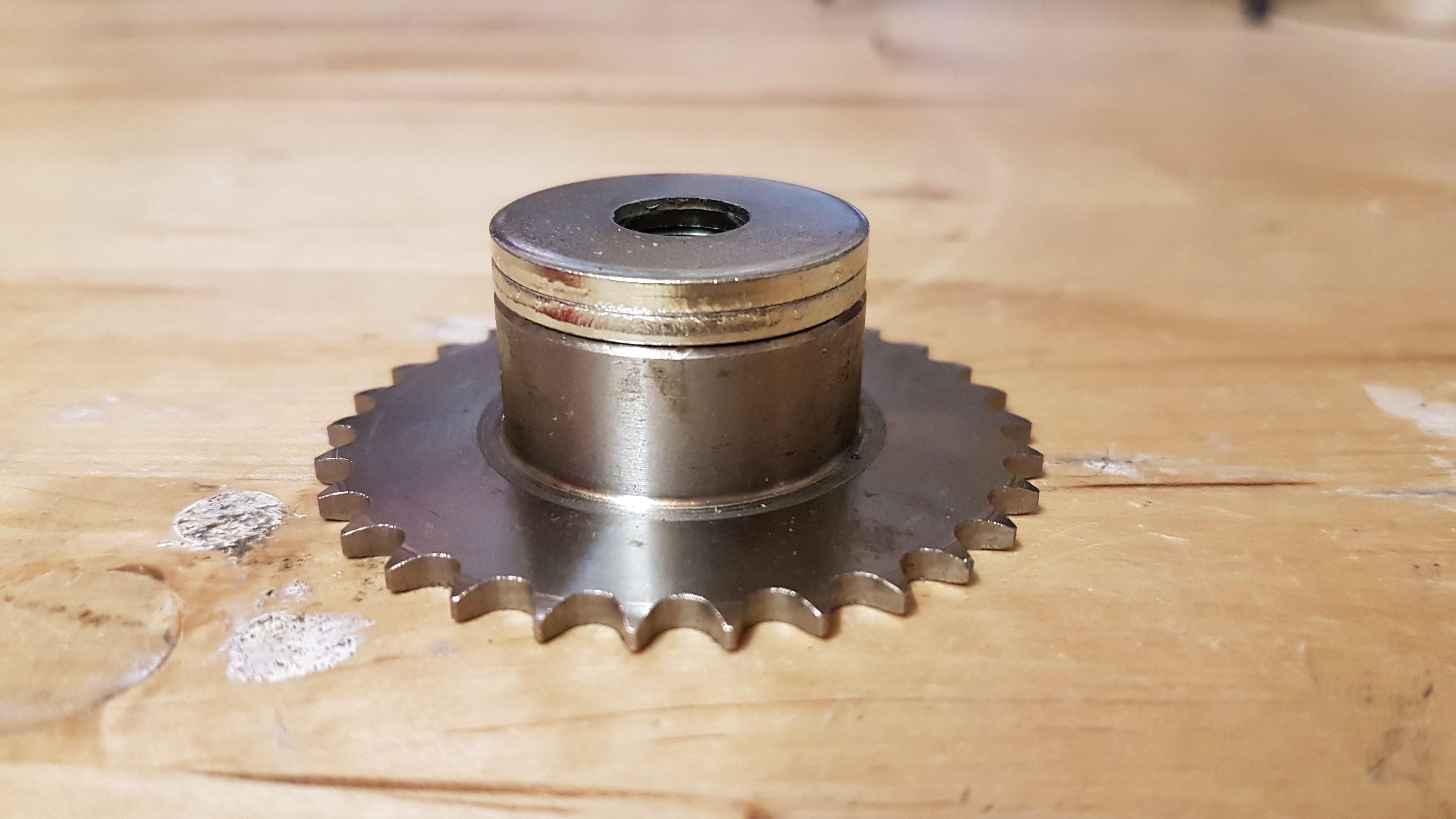
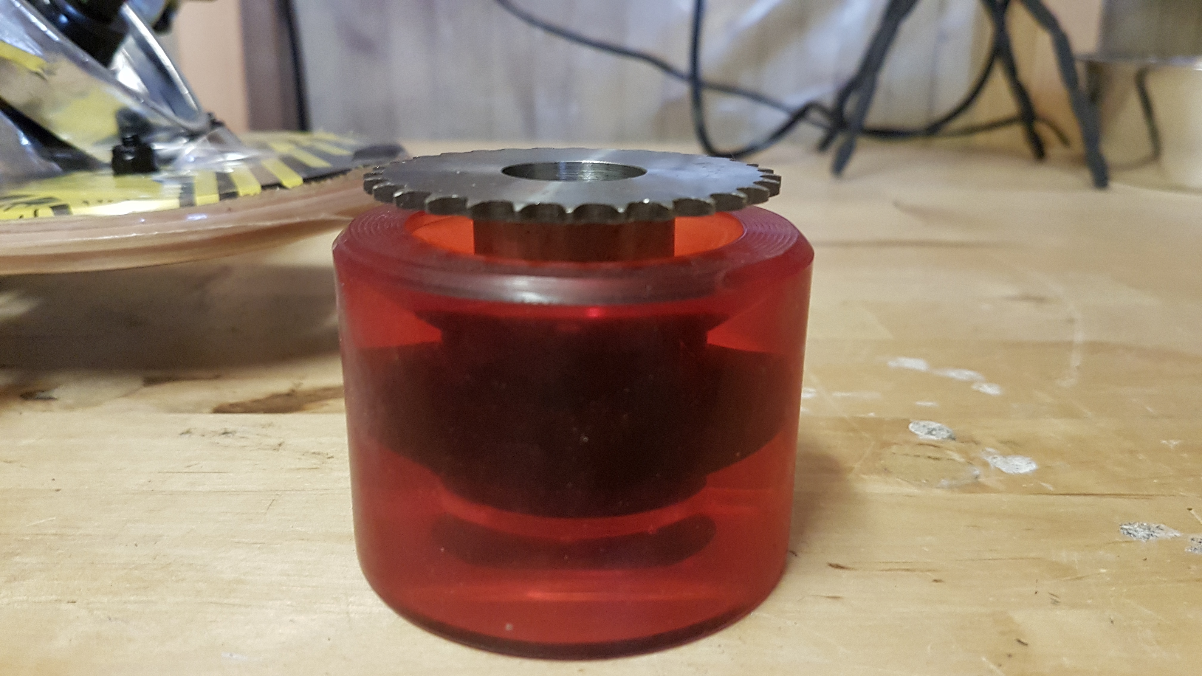
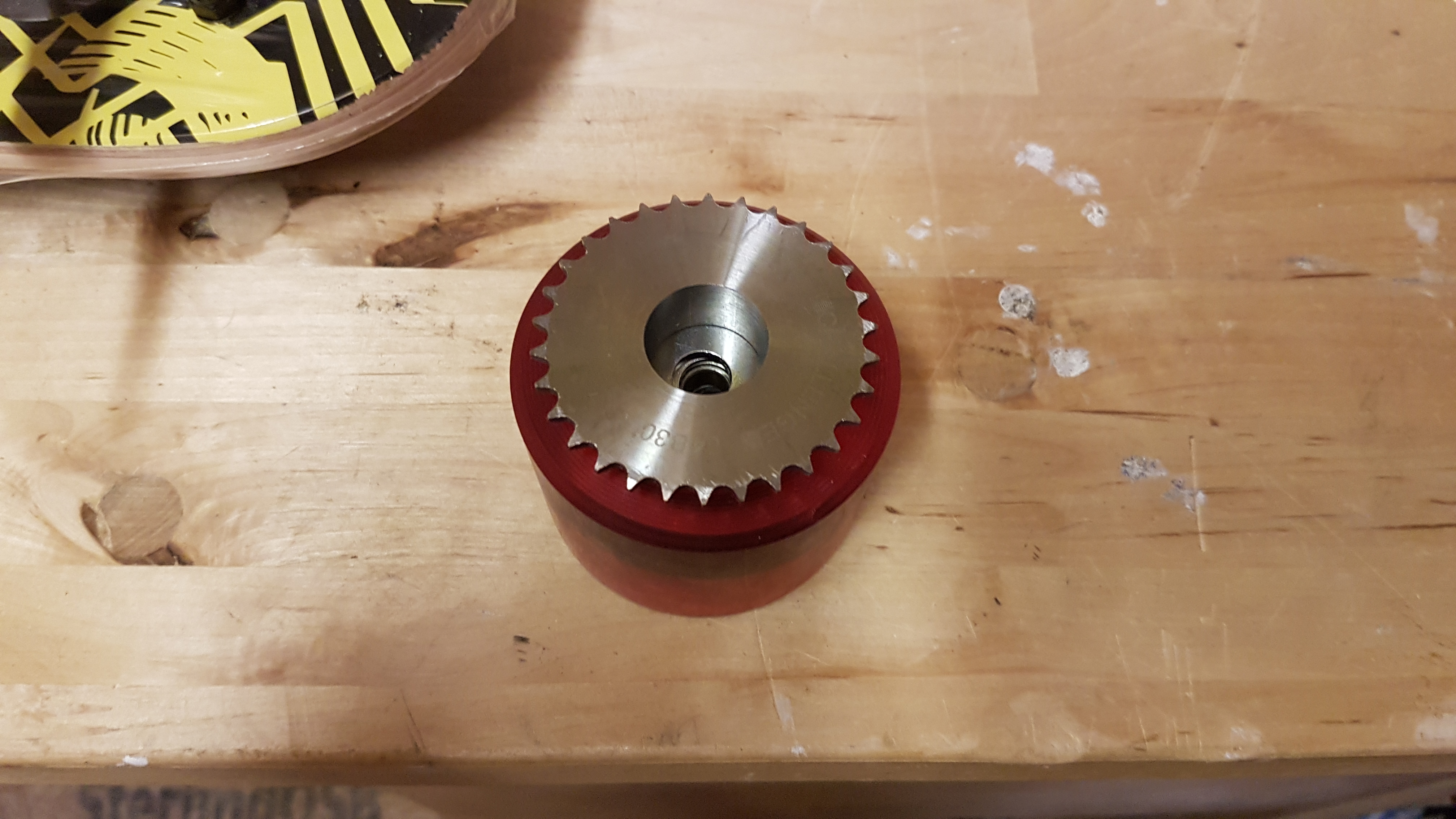
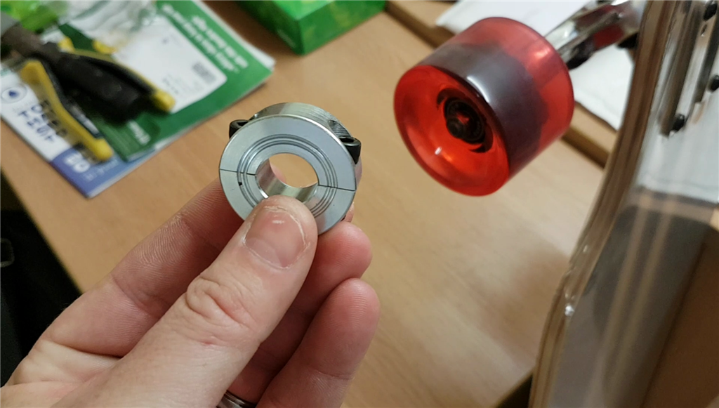
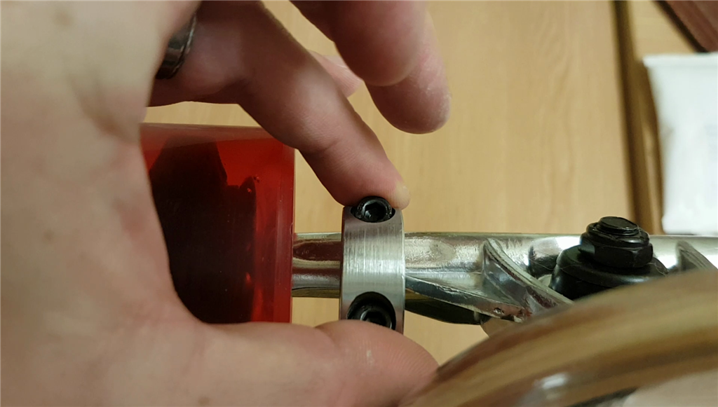
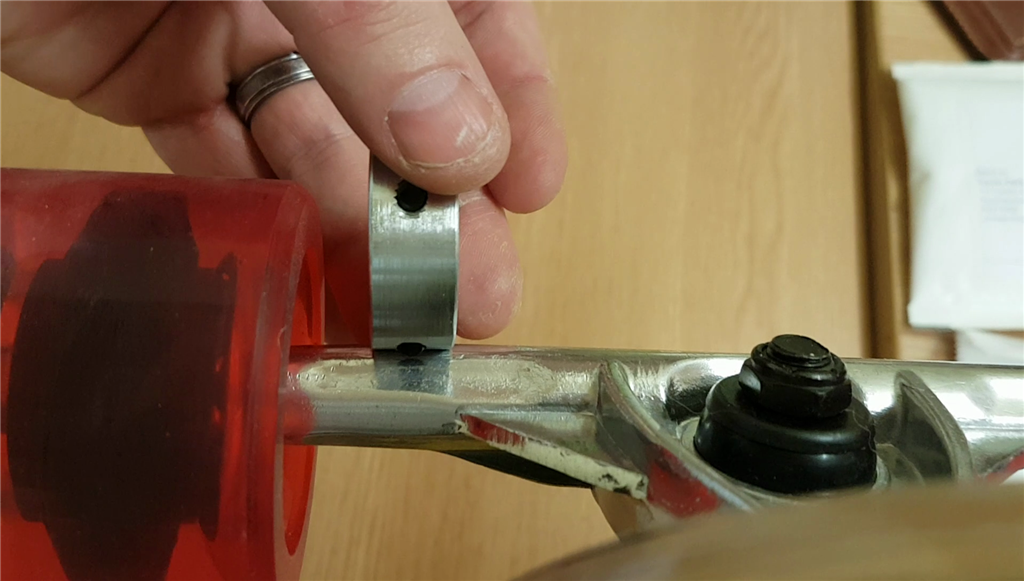
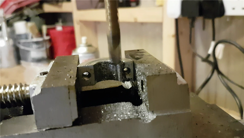
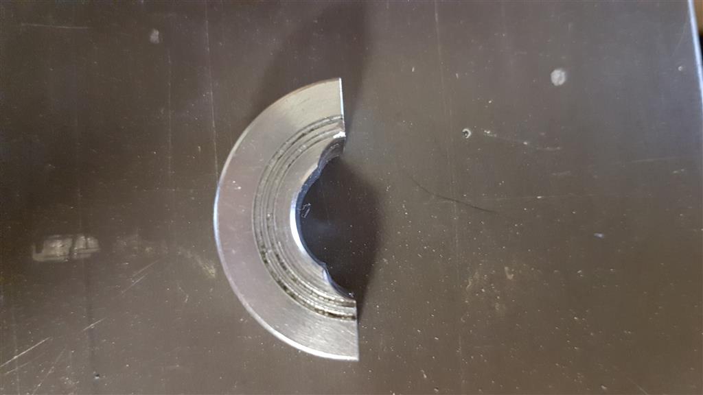
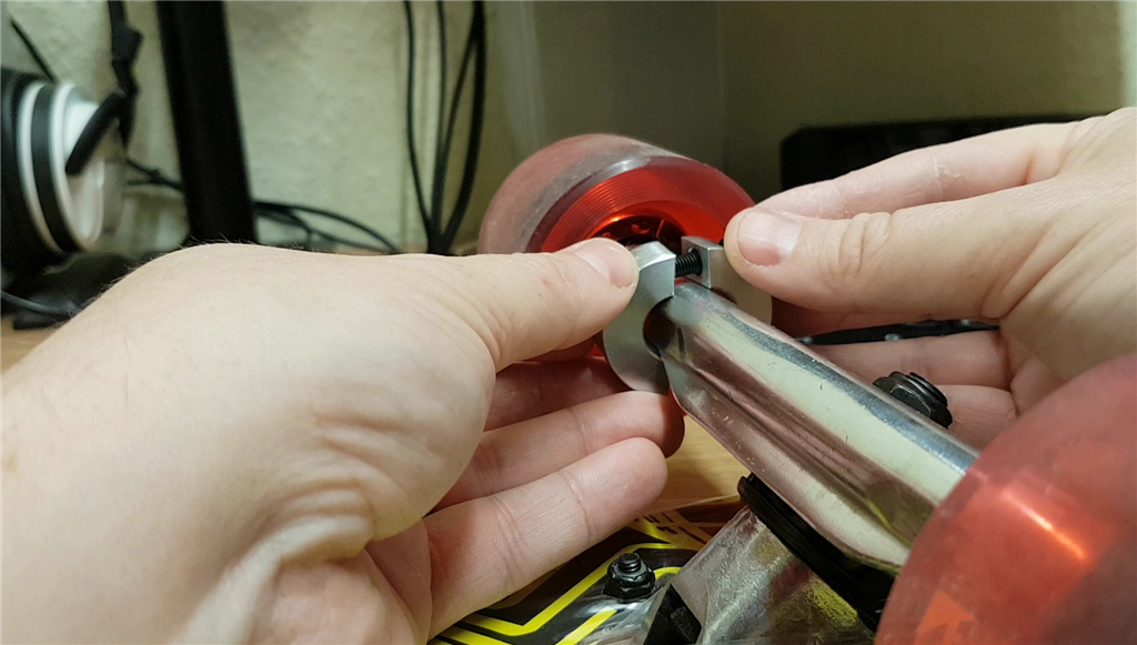
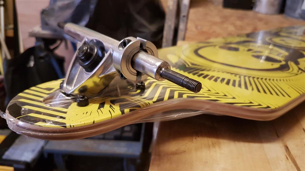
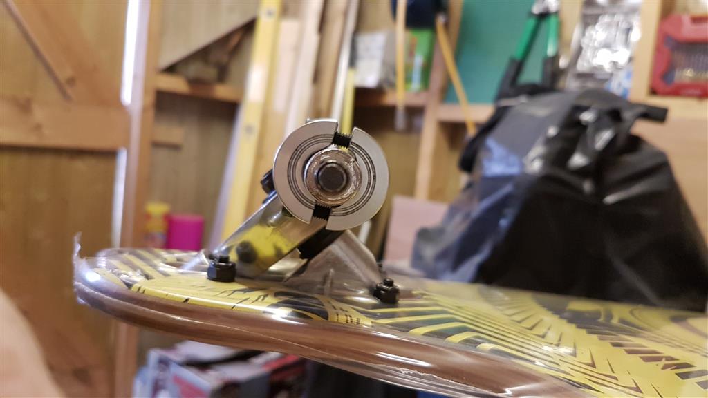
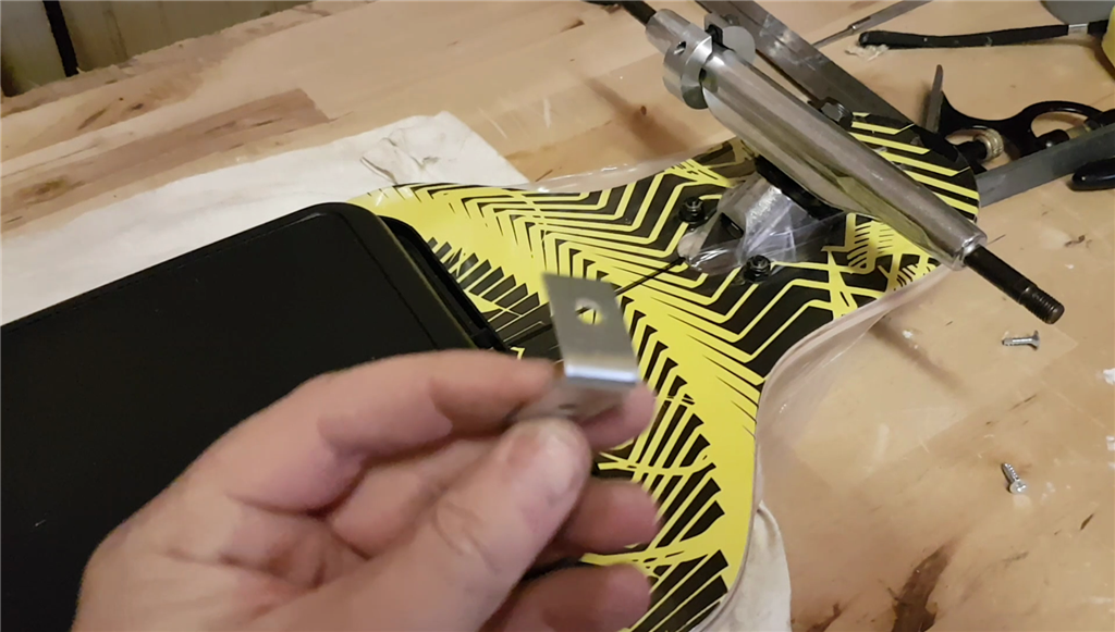
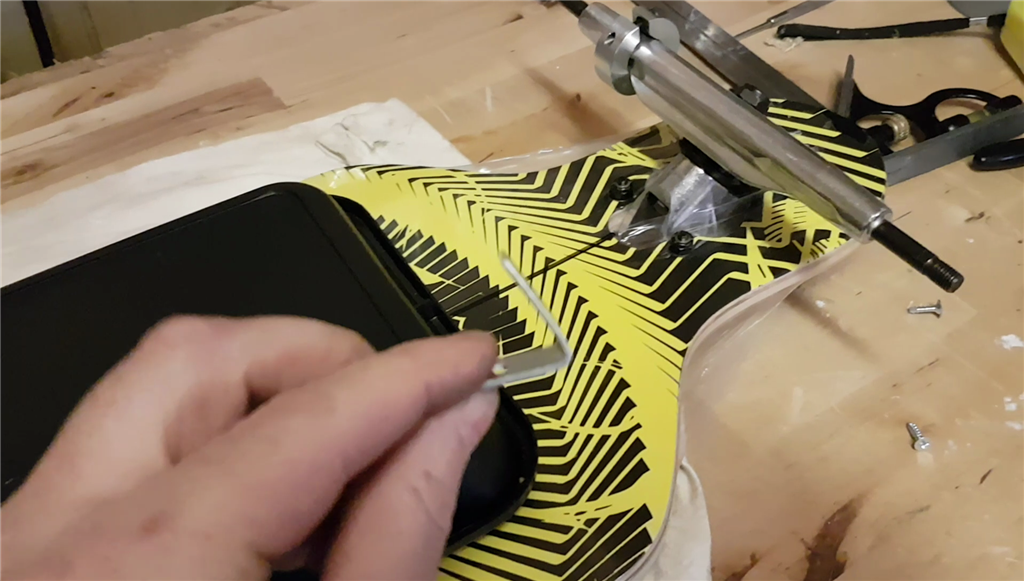
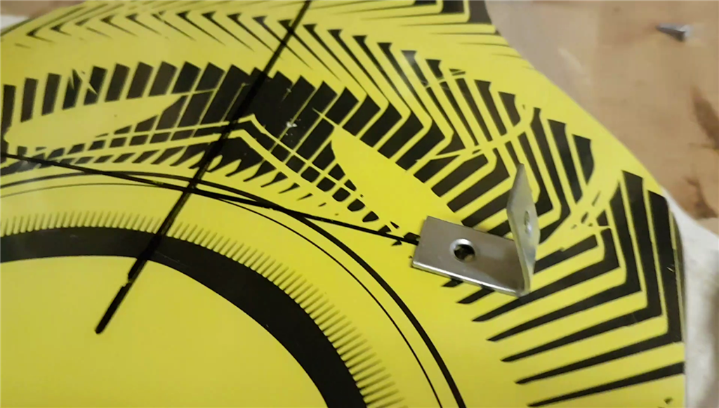
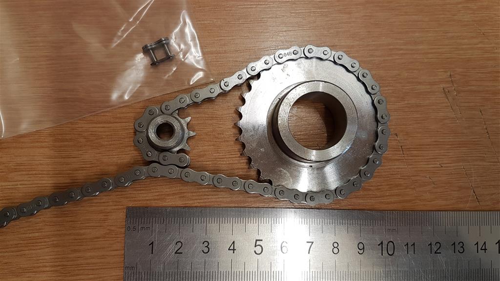
I placed the sprocket on the wheel (once I took it off) to offer it up, the hub of the sprocket wasn't quit big enough to make the outside diameter of it sit far enough away from the wheel to accommodate the chain, so I found a couple of 30mm x 1mm (8mm bore) washers which did the trick and fit perfect!