DIY ELECTRIC LONGBOARD: BUILD CONTINUED...
Thanks for reading my blog, if you haven't read Part 1 already you can find it here...
Now that I have the motor I thought I'd move on to fabricating the motor mount and attempt to attach the sprocket to the wheel.
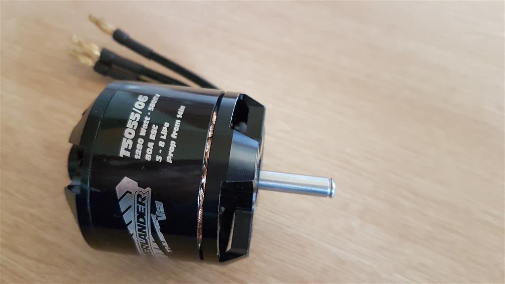
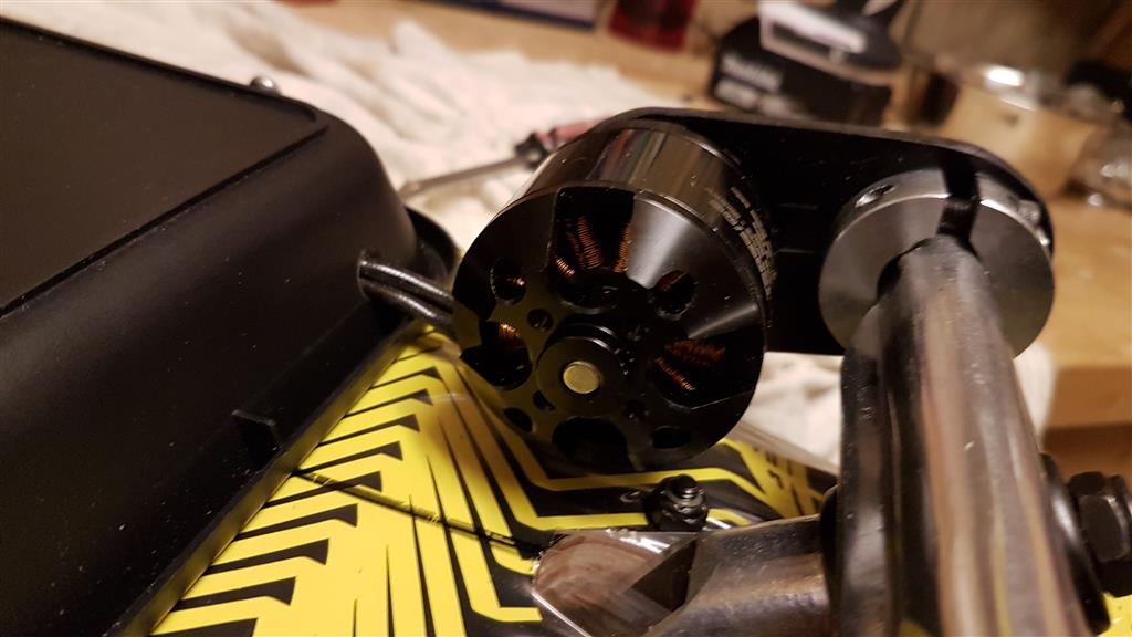
This is the electric motor, it's actually normally used for 1/10th R/C cars or medium sized aeroplanes. It has a low KV rating though (580kv) which means it produces quite a lot of torque, which is what I need when the board has to pull my fat arse along the road!
I got an Overlander Tornado Thumper, brushless outrunner. Outrunners work the best for this type of job.
I got an Overlander Tornado Thumper, brushless outrunner. Outrunners work the best for this type of job.
Some stats for the motor:
- 1280 watt motor
- 10-22 NiMH cells
- 3-8 LiPo cells
- Prop size from 14x6in to 17x10in (larger prop with less cells)
- Shaft Diameter 6mm
- Motor weight 279gm
- Speed Controller Recommended 80A ESC
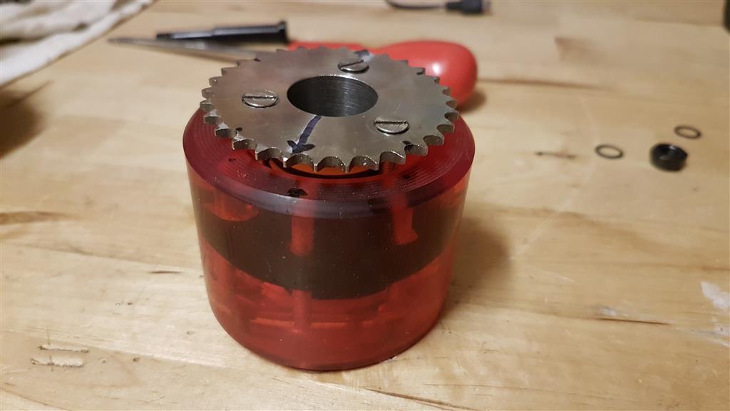
SPROCKET/PINION
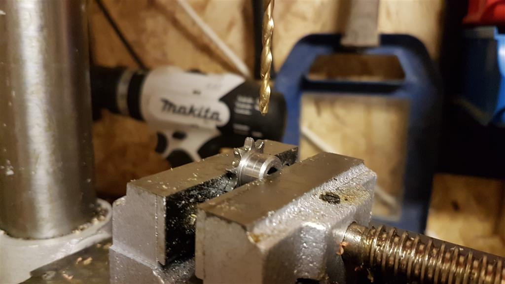
When I bought the sprocket to put on to the motor I got one with a 6mm bore because that was the shaft size of the motor, which is probably the smallest you'd dare go for powering a longboard with a whole person's weight on it, any smaller and you might run in to stripping problems. Although when it arrived, I did have to drill and tap a 4mm hole in it's collar in order to insert a grub screw to connect it tightly to the motor shaft. I also needed to file down the shaft of the motor to have a flat spot for the grub screw to bed down on to.
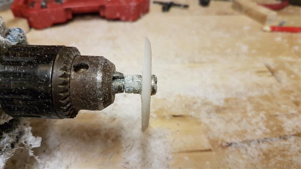
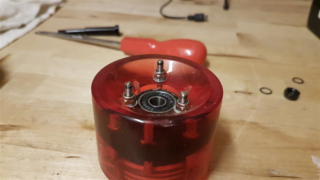
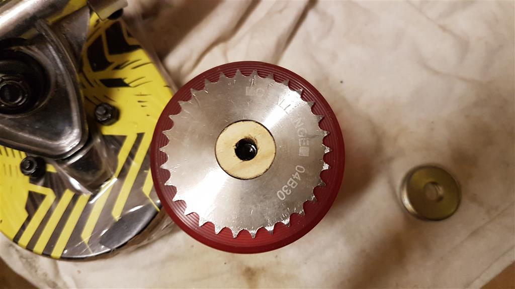
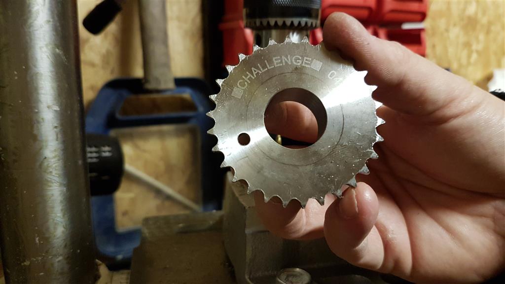
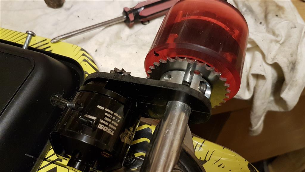
MAIN SPROCKET
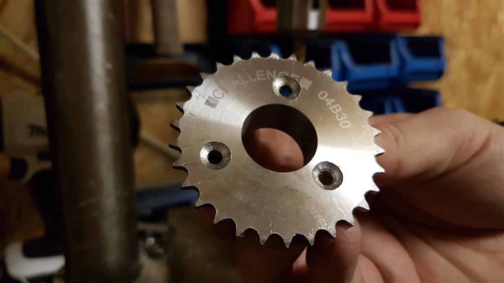
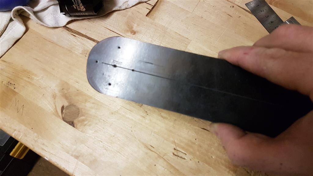
Once I'd done that I moved on to the main sprocket. I decided I only wanted three bolts connecting the sprocket to my wheel, this way it will look better and there'll be less chance of it being offset and there being wobble.
I started by offering it up to the wheel, lining it up and measuring out where three holes would go for the bolts, each 120 degrees apart. The bolts are size M4 @ 80mm long, but that's way overkill, I'll be cutting them down to size. As you can see in the photos, I countersunk the holes because I want it to be flat and flush, I don't like protruding bolt heads. You may see bolt heads in some photos but they're just test bolts.

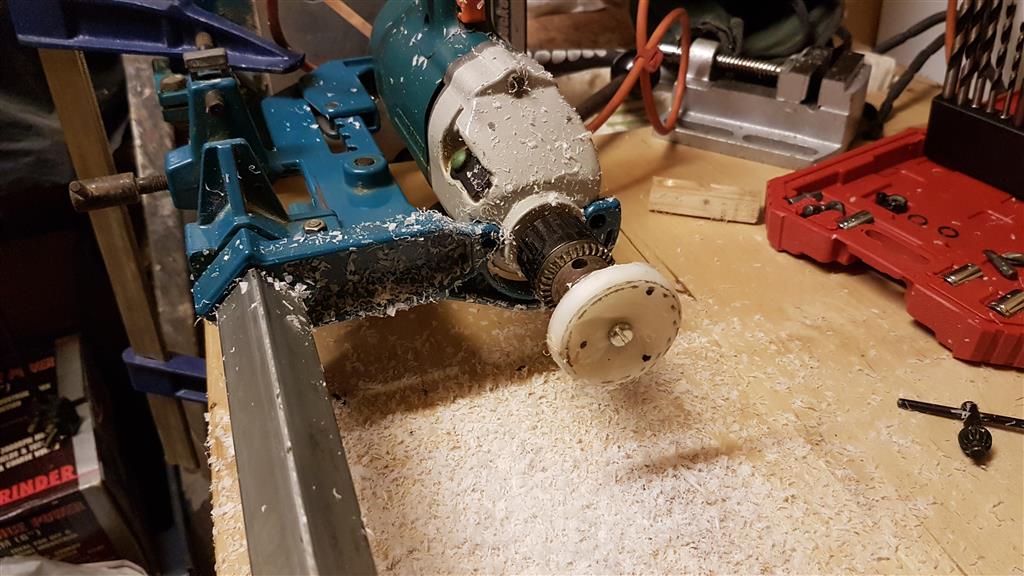
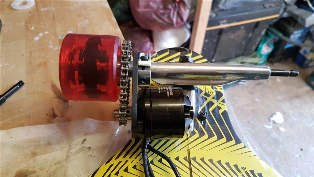
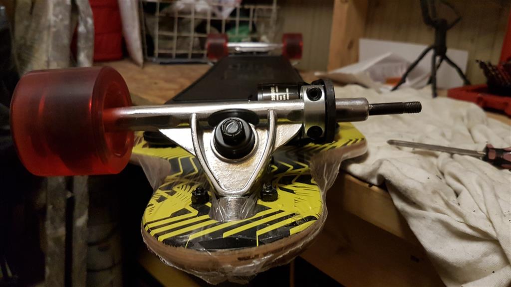
MOTOR MOUNT
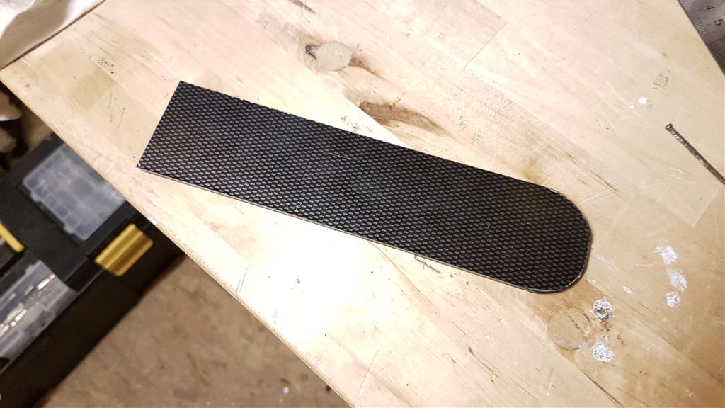
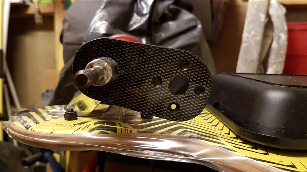
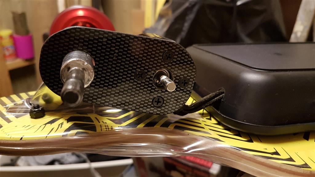
Once that was done I moved on to the motor mount. For this - for testing - I'm using a 50mm strip of carbon fibre-look ABS plastic @ 5mm thick. I do have some 4mm carbon fibre sheet that I'll use for the final mount, but for testing I'm using this cheap ABS.
I worked out where I wanted the motor to sit, how far from the sprocket etc. and how close to the deck from the underneath, taking lots of measurements as I went.
Bear in mind that when you lean on a board the truck twists slightly and the board gets closer to the ground and the truck the more you lean, so I had to take clearance in to consideration with motor position.
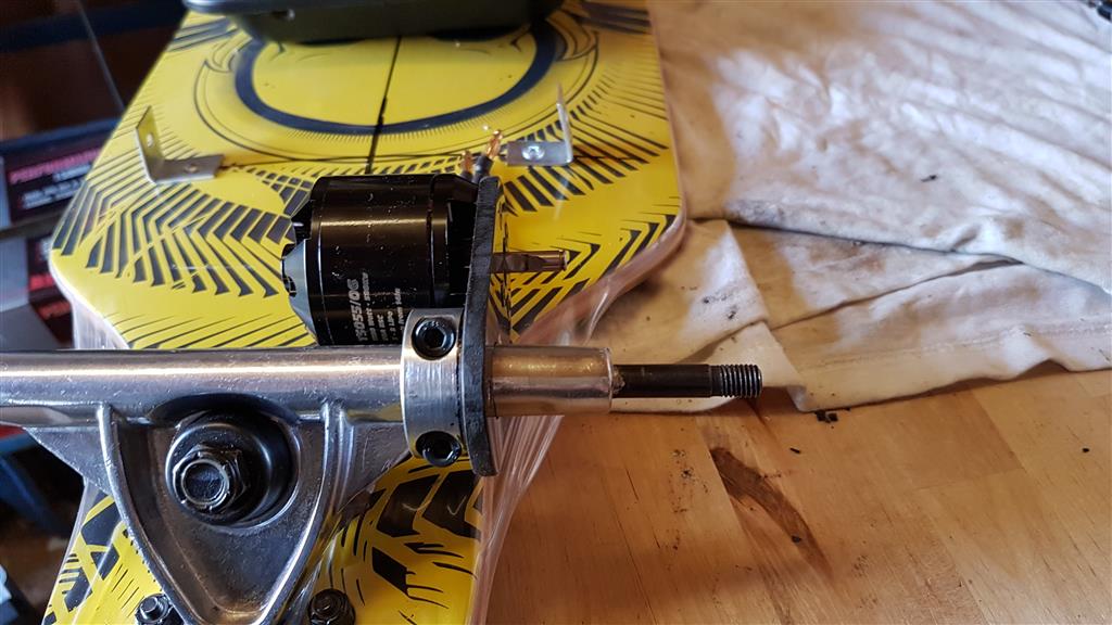
Once I was happy I drilled the holes for the bolts for the motor using it's handy aluminium mounting bracket it came with, for installing it into a plane as a template.
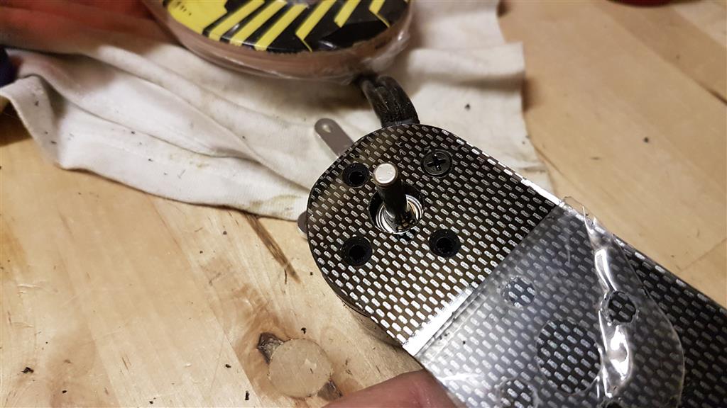

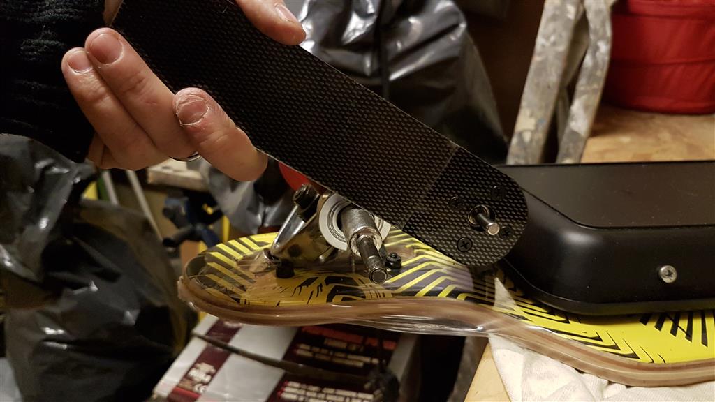

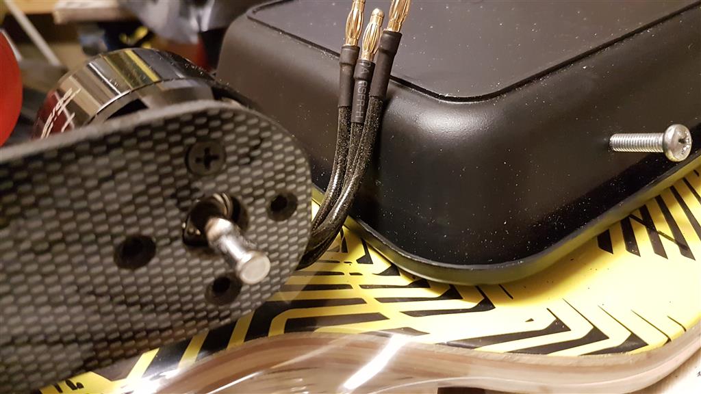
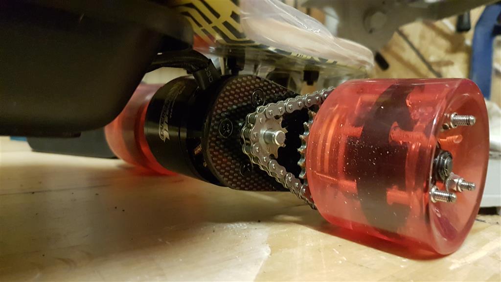
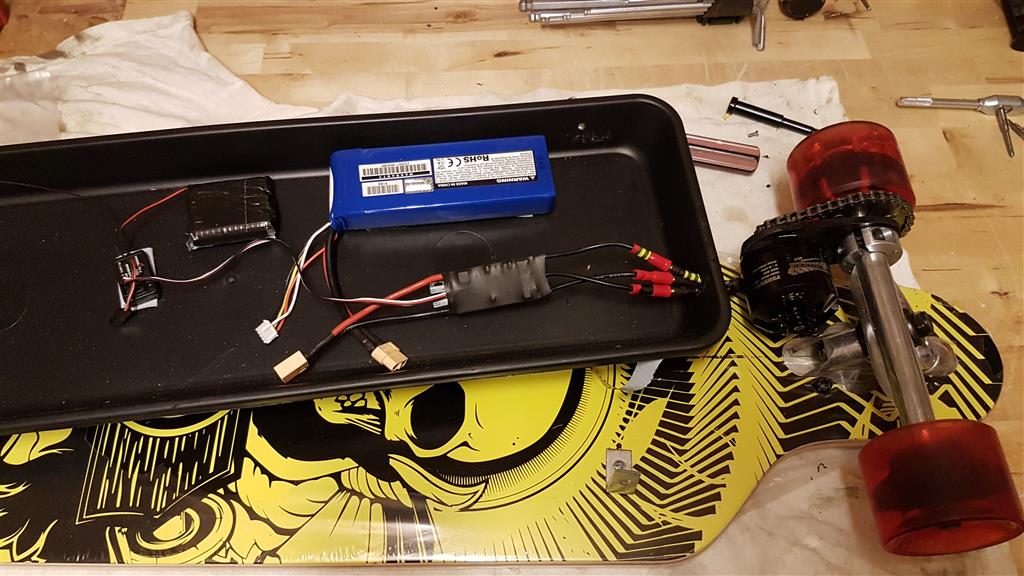
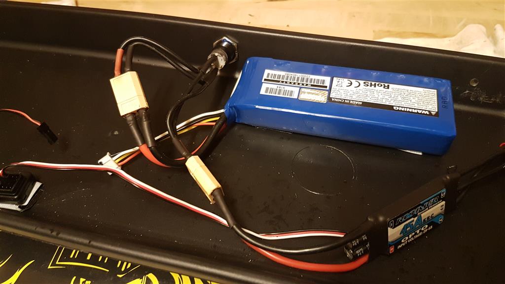
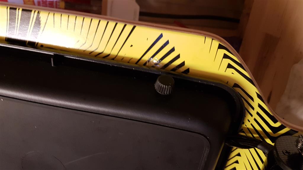
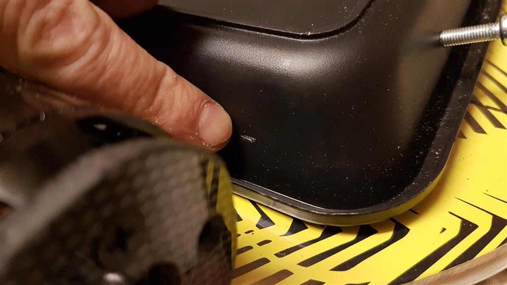
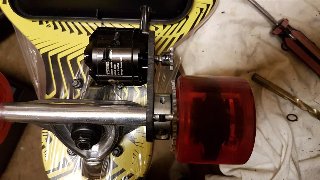
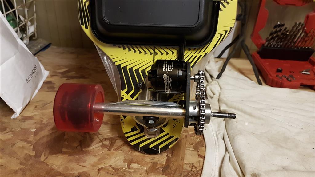
In the last photo above, you can see that the wires for the motor are up against the under-try where all the electrics will be. The next job was to drill a hole (not too big) in that tray in order to feed the wires through which will eventually be connected to the speed controller (ESC).

That looks OK to me, neat and tidy...
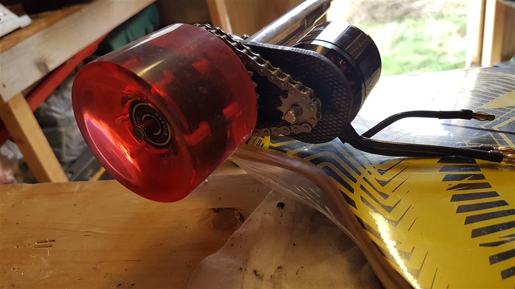
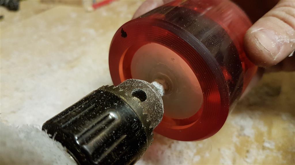
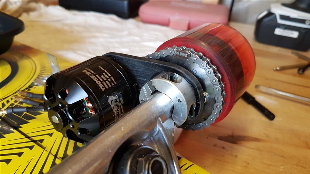
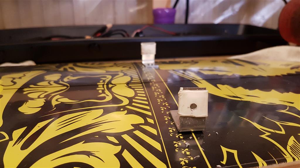
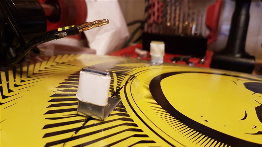
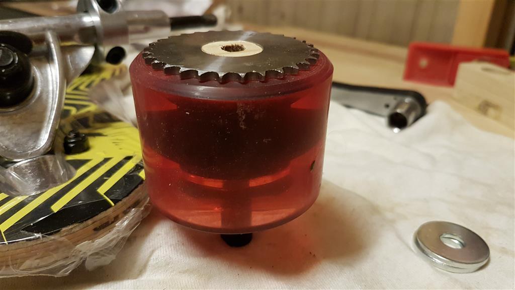
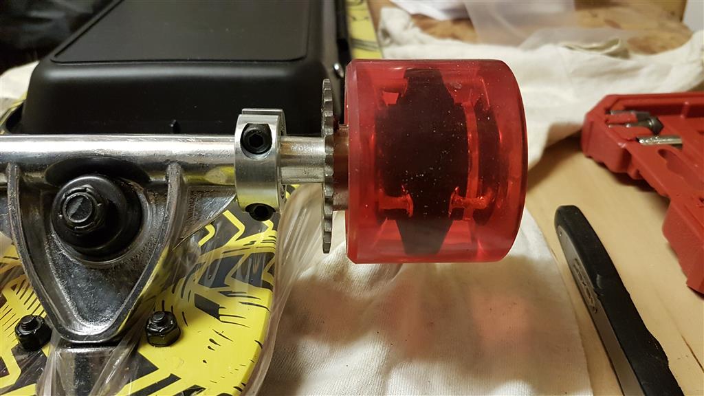
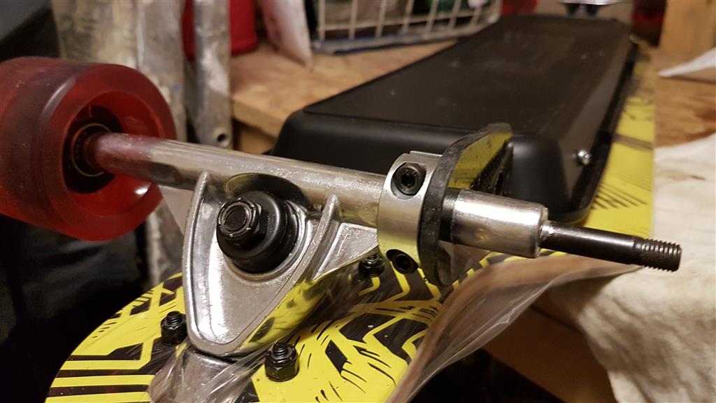
Next I wanted to offer up the sprocket in order to align the sprocket and pinion, and also to try the chain for fit after I'd split it and reduced it's size dramatically!

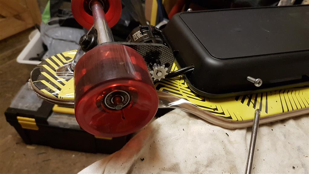
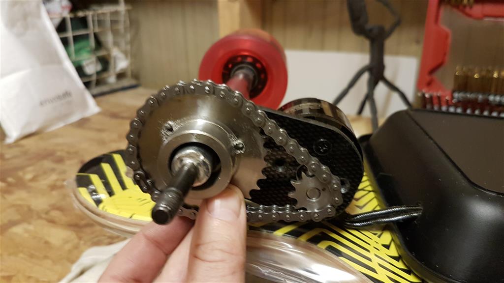
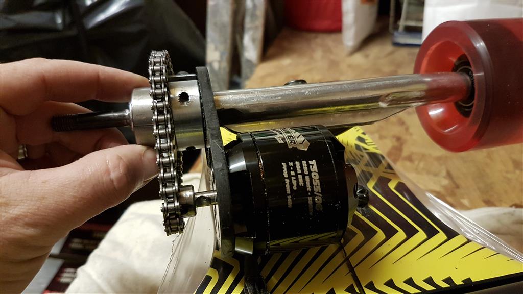
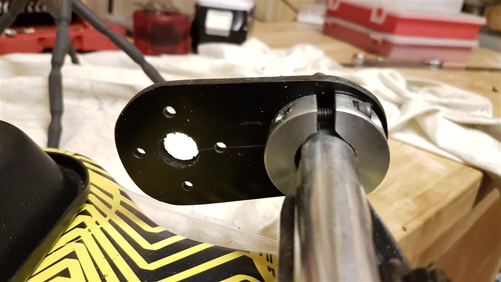
After offering it up etc. I decided that having the collar on the side of the shaft closest to the wheel wasn't the best way, so I flipped it over, putting it on the inside of the truck with the motor mount closest to the wheel instead.
This worked much better and was a much more straight fit between pinion and sprocket.
This worked much better and was a much more straight fit between pinion and sprocket.